mbedTLS library optimisation
Mongoose OS uses mbedTLS library from ARM with several patches:
- RAM usage by each connection. By default, mbedTLS uses allocates >32k RAM for each TLS connection. Mongoose OS uses dynamic buffers, reducing RAM usage per connection down to 1k RAM.
- ATECC608A crypto chip integration. This patch makes mbedTLS to offload crypto to the hardware chip.
- Dynamic CA certificates loading. By default, mbedTLS loads all CA certificates in RAM. Our patch makes it load on demand, saving a lot of RAM. Mongoose OS stores CA certificates in ca.pem file, where you can add your server's CA certificate without blowing RAM usage.
ESP32 flash encryption
Encrypting on-flash code and data is essential:
- it protects from the reverse engineering
- it protects the device credentials, like private keys, being copied and used to get cloud access
ESP32 chip comes with built-in security features, one of which is a transparent SPI flash encryption - for details, see Espressif documentation.
Mongoose OS makes ESP32 flash encryption setup easy. By default, Mongoose OS firmware is flashed in plain-text form:
mos flash esp32                                 # Flash Mongoose OS on ESP32
mos flash-read --arch esp32 0x190000 2000 -     # Dump filesystem area
The flash-read command dumps the flash memory into a file, and the output
can show that the contents is not encrypted. Therefore, sensitive
information like TLS private keys could be easily stolen from the flash.
In this case, we see a part of the device's file system, not encrypted.
In order to enable flash encryption, use esp32-gen-key command. It
enables flash encryption for the next flashing (and sets efuses):
mos -X esp32-gen-key flash_encryption_key fe.key \
  --esp32-enable-flash-encryption --dry-run=false
mos flash esp32 --esp32-encryption-key-file fe.key
That is irreversible - once flash encryption is enabled, you cannot go back.
Note the extra flag --esp32-encryption-key-file fe.key
for the flash command. From now on, a key file is required to re-flash the device.
If the key file is lost, the module can't be reflashed.
After flash encryption is enabled, the very first boot performs
an encryption, which takes a while - up to a minute.
Subsequent boots will be normal, not doing any encryption.
Once the flash is encrypted, one can verify it using flash-read command
to ensure there no plain-text parts are present:
mos flash-read --arch esp32 0x190000 2000 -
It is recommended to use a separate key for each device. The efuses must be set to enable encryption (this is done automatically by esp32-gen-key) and can be verified by running:
mos esp32-efuse-get
A device with encryption enabled should show flash_crypt_cnt : 0x01
If you really wanted to specify the encryption key, possibly your use case is easier with a shared key, you need to set the fuses directly
mos esp32-efuse-set flash_encryption_key=0x0000000000000000000000000000000000000000000000000000000000000000 flash_encryption_key.RD=1 flash_encryption_key.RD=1 flash_crypt_cnt=1 flash_crypt_cnt.WD=1 JTAG_disable=1 download_dis_encrypt=1 download_dis_decrypt=1 download_dis_cache=1 flash_crypt_config=0xf
Substitute an appropriate hex string for the key parameter, ie 0xdabf6bcfcab9d642f22c240e7eda58acf54d305b373990f27ab8241d557a99a8
ATECC608A crypto chip
Often, IoT boards provide no built-in flash protection mechanism. Anyone with a physical access to the device can read the whole flash, including any sensitive information like TLS private keys.
Crypto chips are designed to mitigate that. Their main function is provide storage for private keys, which cannot be read. Private keys are stored inside the crypto chip, and all the crypto operations that require private key, are offloaded to the crypto chip which performs the operation and gives the result back.
ATECC608A crypto chip is designed with additional hardware protection mechanisms to make key extraction difficult. It is an impressive piece of hardware with many layers of protection, and important enough it is quite inexpensive, costing less than 80 cent a piece.
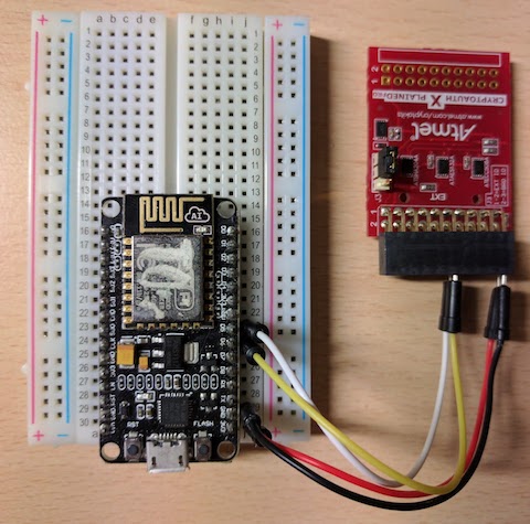
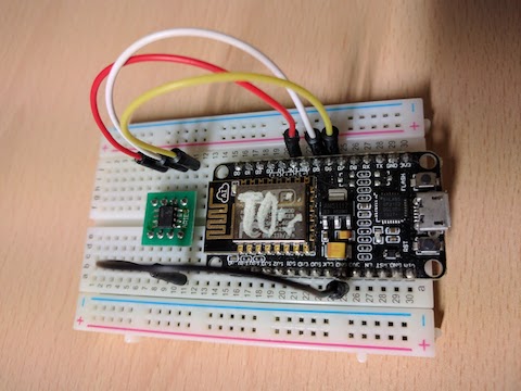
Wiring (ESP8266 NodeMCU example)
Get ATECC608A - either as an ATCRYPTOAUTH-XPRO board which requires no soldering, or a bare-bones ATECC608A which requires soldering.
| Function | ATECC608A pin | ESP8266 pin | NodeMCU pin | ATCRYPTOAUTH pin |
|---|---|---|---|---|
| SDA | 5 | 10 (GPIO12) | D6 | 11 (yellow) |
| SCL | 6 | 9 (GPIO14) | D5 | 12 (white) |
| GND | 4 | Any GND | Any GND | 19 (black) |
| VCC | 8 | Any 3V3 | Any 3V3 | 20 (red) |
Wiring for ATCRYPTOAUTH-XPRO:
Wiring for the bare-bones ATECC608A:
Setup guide
Mongoose OS has native support for ATECC608A security chip. This section is a quick guide to get it up and running. For a more detailed reference, especially of chip configuration, please refer to Microchip documentation.
- The chips leave the factory unconfigured. Blank chip will be detected but crypto operations failing with code
0xf4. Microchip provides their own configuration tools butmosincludes basic commands to get and set configuration as a YAML file. For development you can use our sample configuration. To set it, use the followingmoscommands:
mos atca-set-config atca-test-config.yaml --dry-run=false
mos atca-lock-zone config --dry-run=false
mos atca-lock-zone data --dry-run=false
Note: This only needs to be done once and once locked, chip configuration cannot be changed anymore. You can dump chip's configuration with mos atca-get-config --format=yaml.
Note 2: Sample config is very permissive and is only suitable for development and testing, NOT for production deployments. Please refer to Microchip's manual and other documentation to come up with more secure configuration (we may be able to assist with that too - ask a question on our forum).
- Generate a cert and key as normal. An example below shows a self-signed certificate, but of course it doesn't have to be. The important thing is that it's a ECDSA certificate using P256 curve, since that is what the chip supports.
openssl ecparam -out ecc.key.pem -name prime256v1 -genkey
openssl req -new -subj \
  "/C=IE/L=Dublin/O=ACME Ltd/OU=Testing/CN=test.acme.com" \
  -sha256 -key ecc.key.pem -text -out ecc.csr.tmpl
openssl x509 -in ecc.csr.pem -text -out ecc.crt.pem \
  -req -signkey ecc.key.pem -days 3650
- Write the generated key into the device. Assuming you are using our sample configuration described in the previous section, this is a two-step process:
3.1. Generate and set the key encryption key in slot 4
openssl rand -hex 32 > slot4.key
mos -X atca-set-key 4 slot4.key --dry-run=false
AECC508A rev 0x5000 S/N 0x012352aad1bbf378ee, config is locked, data is locked
Slot 4 is a non-ECC private key slot
SetKey successful.
3.2. Set the actual ECC key in slot 0
mos -X atca-set-key 0 ecc.key.pem --write-key=slot4.key --dry-run=false
AECC508A rev 0x5000 S/N 0x012352aad1bbf378ee, config is locked, data is locked

Slot 0 is a ECC private key slot
Parsed EC PRIVATE KEY
Data zone is locked, will perform encrypted write using slot 4 using slot4.key
SetKey successful.
- Upload the certificate to the device
mos put ecc.crt.pem
- Set HTTP server configuration to use the uploaded certificate and private key from device's slot 0:
mos config-set http.listen_addr=:443 \
  http.ssl_cert=ecc.crt.pem http.ssl_key=ATCA:0
Getting configuration...
Setting new configuration...
Saving and rebooting...
At startup you should see in the device's log:
mgos_sys_config_init_http HTTP server started on [443] (SSL)
And when connecting with the browser:
ATCA:2 ECDH get pubkey ok
ATCA:0 ECDSA sign ok
ATCA:2 ECDH ok
Configuring TLS on device's HTTP/WS server
The system HTTP server has the following configuration options (we've added
comments to the mos tool output):
mos config-get http
{
  "enable": true,         # Set to false to disable default HTTP server
  "hidden_files": "",     # Glob pattern for files to hide from serving
  "listen_addr": "80",    # Port to listen on
  "ssl_ca_cert": "",      # CA certificate for mutual TLS authentication
  "ssl_cert": "",         # Certificate file
  "ssl_key": "",          # Private key file
  "upload_acl": "*"       # ACL for which files can be uploaded via /upload
}
In order to setup one-way SSL/TLS on the system HTTP server, create a certificate, upload the certificate an the key file to the device, and change HTTP server configuration.
How to create a self-signed certificate
openssl req  -nodes -new -x509  -keyout key.pem -out cert.pem
mos put cert.pem
mos put key.pem
mos config-set http.listen_addr=443 http.ssl_key=key.pem http.ssl_cert=cert.pem
mos wifi WIFI_NET WIFI_PASS
curl -k https://IP_ADDRESS     # Test it !
If you want to use mutual (two-way) TLS with the device, follow this procedure to use a self-signed certificate:
Self-signed certificate for mutual TLS
# Common parameters
SUBJ="/C=IE/ST=Dublin/L=Docks/O=MyCompany/CN=howdy"

# Generate CA
openssl genrsa -out ca.key 2048
openssl req -new -x509 -days 365 -key ca.key -out ca.crt \
  -subj /C=IE/ST=Dublin/L=Docks/O=mos/CN=me

# Generate client cert
openssl genrsa -out client.key 2048
openssl req -new -key client.key -out client.csr -subj $SUBJ
openssl x509 -req -days 365 -in client.csr -CA ca.crt \
  -CAkey ca.key -set_serial 01 -out client.crt

# Generate server cert
openssl genrsa -out server.key 2048
openssl req -new -key server.key -out server.csr -subj $SUBJ
openssl x509 -req -days 365 -in server.csr -CA ca.crt \
  -CAkey ca.key -set_serial 01 -out server.crt
When done, copy generated files to the device and reconfigure the server:
# Upload server key, cert & ca cert to the device
mos put ca.crt
mos put server.key
mos put server.crt

# Update HTTP server settings to use mutual TLS
mos config-set http.ssl_ca_cert=ca.crt http.ssl_cert=server.crt \
  http.ssl_key=server.key http.listen_addr=443
From that point on, the device should be accessible via secure Websocket:
# Configure WiFi
mos wifi WIFI_NET WIFI_PASSWORD
mos --cert-file client.crt \
    --key-file client.key \
    --port wss://IPADDR/rpc \
    call RPC.List
Device as a network client
A connected device can be a network client, or network server, or both. For example, if a device provides a RESTful interface, it acts as a network server. If a device connects to an MQTT server, it acts as a network client.
Avoid running a network server on your device for the following reasons:
- It is easy to DoS the device by creating many network connections. Say, a device has 40k of free RAM, and each connection takes 10k, then 4 connections is enough for the denial of service
- A device must implement authentication and authorisation mechanisms that are potentially vulnerable
- A network service code may be vulnerable
- If TLS is used for communication, the connection setup time could be large because of the slow CPU, leading to delays and bad user experience
- TLS certificate management for the local communication could be non-trivial
On the other hand, when a device acts as a client, these problems disappear:
- It is impossible to hack into the device directly because it does not expose any network endpoint
- A device does not care about authentication and authorisation - it is all handled on the cloud side, and secure services like Google IoT Core or AWS IoT would be a good choice for the cloud backend
- The only entity a device should trust is a cloud backend, which is handled by the industry-standard TLS
- No need to keep many network connections, cause a single secure connection to the cloud backend is enough for both management and data flows. This saves precious resources
Securing RPC
RPC is a Mongoose OS mechanism for remote management. Every time mos tool
is fired in a command line mode or in the GUI mode, RPC is used to query the
device - over serial or remotely. Displaying list of files, showing what
hardware platform it is, amount of free RAM, toggling GPIO - it is all RPC.
When a new device is flashed, it is in a default state when all RPCs are allowed for everybody. Several mechanisms are available to restrict the access to RPC services:
- Enable authentication - which users are allowed
- Enable authorisation - what allowed users can do
- Disable RPC for the given channel
- Disable all RPC functionality
Enable authentication
Mongoose OS implements authentication using Digest mechanism, the same as HTTP Digest authentication employs. It works like this - true for both HTTP Digest and Mongoose OS RPC:
- Client sends a request
- If authentication is not enabled, server replies
- If authentication is enabled and client request has authentication data, server replies
- If authentication is enabled and client request does not have authentication data, server sends back an error requesting authentication with a random nonce to prevent replay attacks
- Client repeats the request with the authentication data created with the server's nonce
In the case of HTTP, an authentication data is sent in the Authorization:
HTTP header. In the case of RPC, an authentication data is sent as an
additional auth key in the RPC frame.
The authentication is enabled by creating a passwords file in the htdigest
standard format and setting it in the configuration.
The format of the passwords file is the same as for the HTTP Digest
authentication, and it could be managed by the Apache's htdigest.
This is an example that creates a passwords file with user joe,
uploads that file to the device, and configures RPC to use it:
htdigest -c rpc_auth.txt myproduct joe
mos put rpc_auth.txt
mos config-set rpc.auth_domain=myproduct
mos config-set rpc.auth_file=rpc_auth.txt
Enable authorisation
RPCs that are authenticated, could be checked against the ACL file to determine whether a given authenticated user can access an RPC:
mos put rpc_acl.json
mos config-set rpc.acl_file=rpc_acl.json
The format of the ACL is similar to the config management ACL. Here is an
example of rpc_acl.json file:
[
  {"method": "FS.*", "ch_type": "GCP", "acl":"*"}
  {"method": "SYS.*", "ch_type": "WS_in", "acl":"*"}
  {"method": "FS.*", "acl": "+user1,-user2"},
  {"method": "*", "acl": "-*"}
]
Note, you can optionally specify communication channel based ACLs via the 'ch_type' parameter. If in doubt what your desired channel is referred to, send a RPC call to the device and look for a log line similar to mgos_rpc.c:389 Called 'RPC.List' via 'WS_in', ACL: '*'. Generally the human friendly variable is specified in each rpc library, ie for GCP it looks like:
static const char *mgos_rpc_channel_gcp_get_type(struct mg_rpc_channel *ch) {
  (void) ch;
  return "GCP";
}
Disable RPC for given transport
If the transport is disabled, that's it! RPC transports are serial, HTTP/RESTful, Websocket, MQTT, Bluetooth. This disables HTTP transport:
mos config-set rpc.http.enable=false
Disable all RPC functionality
This is the most radical method. Remove rpc-common library, and all other
rpc-* libraries from your mos.yml. That totally removes RPC functionality
from the firmware.
Note, however, that the RPC security is determined by the security of its transport. For example, RPC over AWS IoT service uses secure, authenticated AWS IoT mechanism, utilising mutual TLS and elaborate policy infrastructure. Thus, encryption, authentication and authorisation of the RPC channel is provided by AWS. Such an RPC channel is highly secure. The opposite example would be an RPC over plain HTTP/RESTful, not authenticated and not locked by authorisation, wide open to the world.
An alternative to RPC for the remote management could be a mechanism provided by the cloud backend - for example, AWS IoT device shadow, or Azure device twin, or Google IoT Core config/state objects, etc.
edit this doc